

So we decided that the easiest way to meet his requirements was to build a custom servo motor, using a high-torque DC motor. All driven by a signal intended for a standard hobby-grade servo.
#Servo motor arduino schematic full#
Not only does it need to have a lot of torque, it also has to be able to turn two full revolutions (720 degrees) instead of 180 degrees. Jeremy and I were chatting, and he mentioned that he required a very large servo motor for one of his projects. If you want to know anything about mechanical engineering or working with motors, then Jeremy is the fellow you need to know. For the few of you who are not familiar with Jeremy’s work, he is a mechanical wizard who builds amazing projects in his workshop, many of them using 3D-printed or reclaimed materials. I’m sure most of you are already familiar with Jeremy Fielding through his YouTube Channel. In fact, I know someone who requires a custom servo motor. A custom design, based upon your specific needs. The answer, of course, is to make your own servo motor.

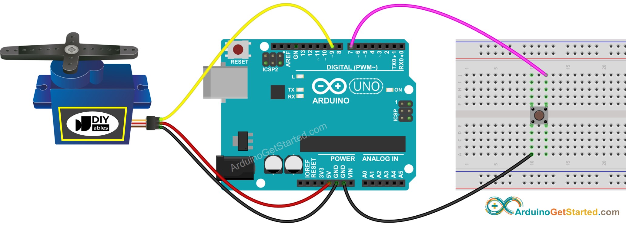
And what if you need a large amount of torque, greater than that provided by inexpensive hobby servo motors? The most common hobby-grade servos rotate 180 degrees, some models are available that have 270 degrees of rotation.īut what do you do if you want a smaller, or larger, amount of rotation? It’s entirely possible that you might want to rotate more than 360 degrees. The larger the motor, the greater the torque, but this gain comes with a corresponding price increase.Īnother limitation is the range, or degrees of rotation, that these motors are made for. The biggest limitation with hobby-grade servo motors is the amount of power, or torque, they can provide. Smaller, hobby-grade servo motors (sometimes called “RC Servo Motors”) are much more affordable, but they have their limitations. Large industrial servo motors use sophisticated controllers and cost quite a bit of money. You just specify the angle of shaft rotation, and the servo motor will oblige by moving into that position. Unlike stepper motors, which also have controllable shaft positions, servo motors don’t need a reference point to start with. Servo motors, for those not familiar with them, are motors whose shaft position can be precisely controlled by an external signal. They are used in all kinds of industrial applications as well. Then, connect the servo motor to +5V, GND and pin 9.įor the Sweep example, connect the servo motor to +5V, GND and pin 9.Ĭontrolling a servo position using a potentiometer (variable resistor).Servo motors are essential components when working with robotics, model aviation, and other animated projects. Knob Circuitįor the Knob example, wire the potentiometer so that its two outer pins are connected to power (+5V) and ground, and its middle pin is connected to A0 on the board. The signal pin is typically yellow or orange and should be connected to PWM pin on the board. The ground wire is typically black or brown and should be connected to a ground pin on the board. The power wire is typically red, and should be connected to the 5V pin on the Arduino board. Servo motors have three wires: power, ground, and signal. You can also visit the Servo GitHub repository to learn more about this library. The second example sweeps the shaft of a RC servo motor back and forth across 180 degrees. The first example controls the position of a RC (hobby) servo motor with your Arduino and a potentiometer. In this article, you will find two easy examples that can be used by any Arduino board. The Servo Library is a great library for controlling servo motors.


 0 kommentar(er)
